Thursday, October 19, 2023

Time-travel to Japan and an aluminum Perfecscope

The late-model Perfecscope is mostly made out of aluminum. By 1900 aluminum had become relatively cheap, and a viable alternative for the wood and leather these things would previously have been made of. Another more-modern trait of this stereoscope or stereoviewer is that the hood and lens-holder parts are also glued together.

That gluing makes this about as far as it can be taken apart for cleaning, without resorting to more drastic measures (e.g. boiling water). The handle-bracket had been bent out-of-shape, but fortunately could be bent back without breaking.


The wire-loops that hold the stereocard on the sliding holder were lost probably decades ago - instead there were bendy lengths of brown electrical-wire. These were pulled off and replacement loops were bent from an old knitting-needle. Nickeled copper fuse-wire might have been better, and easier to work, but this'll do. (Knitting-needles are plentiful in thrift stores and are a useful source of odd-size rod material.)


The velvet rim around the hood had come apart and was also very dirty. This rich purplish-red is probably a decent match, taking into account how much the original is faded.


Glueing a ~1/2" wide length of red velvet around the rim (glue-stick glue) finishes the stereoviewer, and makes the aluminum hood much friendlier on the face.


The bottom of the stereoscope states it is an H.C. White 'Perfecscope', with a patent date of October 15, 1895. That would refer to US patent 548,149 by Hawley C. White himself. In this patent he claims an improved shape of the hood to better match the contour of the face with the benefit of reduced light-leakage. (Manufacturing such an improved shape is probably made easier by using aluminum.)


The decorations on the hood also have the medallion of the Exposition Universelle of 1900 with a small image of the Grand Palais. The slider has an extra patent date in 1904, so this Perfecscope specimen probably dates from some time between 1904 and, say, 1914-ish.


 Today it's again ready for viewing stereoviews - ready for Virtual Reality time-travel to a century ago :-)


Slotting some old stereoscope cards in the holder's new knitting-needle guard-loops, and it transports you right to early 20th century Japan!:


Sunday, October 8, 2023

Во избежание ошибок... (To avoid mistakes...)

Written on a brass label, right next to the crank-handle:

Во избежание ошибок, 
начан оборот, 
добыл ручку до kонца.

With the wonders of the information age and the internet, this label can be read approximately as:

To avoid mistakes, 
when turning started, 
get the handle to the end.

This makes clear - the calculator does not have the protection against reversing direction half-way through a turn. Doing so would indeed mess-up the results of a calculation, so an instruction to complete a turn when started.

This is a relatively early Feliks (Феликс) calculator, model A3 and was made in Moscow probably around 1930. As is well-documented, a few years after the revolution of 1917 the Odhner factory in St. Petersburg was dismantled and moved to Moscow. From the early 1920s (?) the Arithmometer continued to be made there, in the late 1920s new models A2 and A3 were introduced. From about 1928 the machines were made by the "state plant of calculating machines named after Comrade Dzerzhinsky" and were labeled "Feliks".


This machine has serial number 52284. Whilst there isn't much clear serial number data for the machines produced by the factory in that period, from its features and labelling it most likely dates to the 1928 - 1932 range.

Around 1931/33 (?) an updated model was introduced with the characteristic 'corner-feet' baseplate. This basic Feliks-model was then manufactured for decades. After the Moscow factory was closed in 1941 and moved, manufacture of the Feliks starts again in the Kursk Calculator Factory in the late 1940s to continue well into the 1970s.

This A3 still has many of the recognisable design features of the original Arithmometer, it still is very much an Odhner Arithmometer. Although simplified, the drum is also still made of brass and steel. (Later designs replace brass with cheaper zinc-alloy and have a general further lowering of build-quality.) The mechanism is basic, functional - without much in the way of interlocks or safety.


The calculator feels fairly 'rough', with large tolerances on movements. (Compared to the heavy precision of a contemporary Brunsviga Nova, it feels positively shoddy.) Despite that, it does work and is a useful calculator. Its 'build' requires a bit more care from the operator perhaps, but will have made it much easier to manufacture and to maintain the calculator. 


The calculator has quick clearing; a sliding bar under the front of the top-cover can be slid sideways to block the slots and a quarter-turn of the crank then pushes all levers back to zero. On Odhner machines this quick-clearing disables the full-turn safety to enable the quarter-turn-and-back. The Russian machine solves this problem by simply leaving out this safety completely. Hence the extra warning label instead.

The labeling on the calculator gives extensive information on its source.

мснх   рсфср 
трест тoчной пеханиыи
гос. завод счетных mашин
им. тов.  Дзержинсного
москва

The мснх means the Moscow Soviet for National Economy and the рсфср is Russian Soviet Federative Socialist Republic. Then; 

trust for precision equipment
state factory of calculating machines
named after comrade Dzerzhinsky
Moscow

With Феликс as a 'brand'.

Apart from cleaning the machine, the detents for the carry-levers needed to be repaired. The small springs that hold the carry-trigger levers were broken on several columns - this caused the machine to make errors especially in subtraction. Removing the carriage is fairly straightforward, once the left side-cover of the carriage is unscrewed and rotated to allow the carriage to pass the counter-finger!

Then the rod that holds all the star-wheels for the result-register can be withdrawn, releasing all the carry-levers.

The carry-levers are held in position by a detent that is a small rod, spring-loaded in the lever. This chisel-ended rod pushes against the rod that holds the star-wheels.


In keeping with the general 'carelessness' of this machine, the spring-ends are not closed and merely consist of cut lengths of spring. Several of these had broken (inferior quality?) and the two ends wound into each other. In operation this caused the lever to be pushed back by the carry-pin before performing a carry - thus leading to errors. 


Fixed by separating and closing the ends of any broken springs and then all re-mounted. After this repair, calculating 525 - 7 again gives 518 instead of 528.

New 3D-printed rubber feet were fitted and one missing screw added to mount the bottom plate. This bottom plate is a bad fit, askew the base-plate. This is because the holes in the plate are stamped off, as if the plate was not placed properly in the stamping tool. It could be rectified by filing the holes larger, but was left as is - in keeping with the general character of this old Soviet-made calculator (i.e. its apparent 'careless' build-quality).


The Feliks clearly shows shared Odhner Arithmometer design-origins with the Swedish-made Original Odhner calculators. Compared to these Swedish calculators the Feliks hasn't developed much from the Arithmometer design near the end of Odhner in St Petersburg - in fact it probably regressed a bit. And then from the late 1930s it stayed essentially unchanged until the end of production in the 1970s. It even kept the by-then decidedly quaint wing-nuts until the very end of production.


When seen side-by-side with a 1930s Swedish-made Odhner, the overall difference in build-style is noticeable - on the Feliks it all works but there is just a general 'roughness' about the machine.

Now cleaned, preserved and operational again - avoiding mistakes :)


Saturday, September 30, 2023

More Zamac-trouble on a Mignon (and how to remedy)

Yet another Mignon, but this one with a serious Zamac-problem. (A small flock of Mignon Modell 4's have been passing by - giving good opportunity to learn how these can look fine and still be completely broken. Also to learn how these come apart - and go together again.)

The horizontal bearing on this machine was stuck solid in the cast-iron forked-lever from internal swelling. This meant that this Mignon could not type, as the index then won't budge vertically. When trying to remove this bearing to fix by sanding down, it unfortunately completely crumbled.


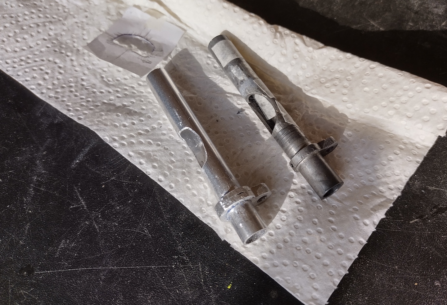
Then the only way to make the Mignon index-typewriter functional again, is to make a new replacement part. The dimensions of the horizontal bearing are metric and fairly standard; it essentially is a tube of 10 mm diameter with 8 mm internal diameter and 80 mm long. It has a flange to fix it to the main cross-casting, a large cut-out to accommodate the gear and one 'internal nail' to lock the rack.

The local DIY-store had 10 mm aluminium tube with 1mm wall-thickness and 2 mm thick strips of aluminium too. One metre lengths of both - to allow for several attempts at making replacement bearings :)

To get the pattern of the cut-out, papper was wrapped around the taped-together original. With a soft pencil, the cut-out was traced, like a brass-rubbing.


The pattern then cut out of the paper and traced onto a length of the aluminium tube. (A bit of extra length to allow clamping without damaging the bearing-surfaces.)


The pattern for the fixing-flange was also sketched and glued to 2 mm thick aluminium. The diameters of the holes are 10 mm (obviously) and 4 mm at a 10 mm pitch. The lug at top is 8 mm wide. This flange should be 3 mm thick. The DIY-store only having 2 mm strip, it'll be doubled to 4 mm.


All material having been marked, then patterns were drilled, sawed and filed. A lot of filing, actually. But then at the end of the filing, there is a replacement horizontal-bearing made out of solid aluminium.


As can perhaps be spotted in the image of the two side-by-side, I made a mistake when glueing the flange in-place on the tube (cyanoacrylate). It is placed ~1.5mm too close to the near edge. Another attempt new-part could be made, but after also shortening the far-end by ~2 mm  it's still functional and symmetrical. (Next time I'll measure twice before gluing once.)

At the very bottom of the fixing-flange a ~1.5 mm through hole must be drilled. From the inside, a short nail is driven into this hole. The ~4 mm head of this nail works as a guide for the gear-rack to stay aligned with the gear-wheel. Not an obviously visible feature of the Mignon mechanism, that nail.


The drawn 10 mm tube is a perfect fit for the cast-iron fork-lever, and allows the mechanism of the Mignon to again swivel back-n-forth for the vertical axis.

Also replacing the pin in this machine's shaft with a brass M2 bolt and nut (just visible), this Mignon index typewriter is again fully functional. Still not a speedy machine, but it writes again. To finish it off, the lettering of the ruler was touched-up and the machine given an overall polish. 


A fine machine. (Still wish that they hadn't used Zamac!)

Friday, September 22, 2023

Replacing a pin with an M2 screw on the Mignon index typewriter

To take apart the actuator arm of a Mignon index typewriter, a soft-steel pin has to be removed from the hollow main actuator rod. This 2mm pin holds the 'plug' with the ball-on-a-needle that is the vertical type-alignment bearing. Only when that is removed, can the parts be taken apart further; the actuator arm in bits:


This pin is in an awkward position. Pins are unpleasant to remove anyways, but this pin is very close to the delicate casting of the arm-assembly. Any stray hammer-tap on that part and it would shatter for sure. 

Also the horizontal bearing-tube is concerning; this also seems to be a fragile Zamac casting. Over time the material can swell and the part will then be very hard to slide out of the cast-iron forked-lever. On this machine only filing down of the centre-section was needed to get it out.

Putting it all together again, the needle-plug was fixed in the actuator-rod not with the pin, but with an M2 screw and nut. 


The brass M2 screw is a very tight fit (scraping), leaving no play between the parts. (Any play would introduce vertical type-alignment variation.) This screw is not authentic, but is normally not visible from the outside. More importantly; an M2 screw won't need hammering close to fragile Zamac castings and will make future repairs so much easier.

Also the soft pin that locks the horizontal-rod (right-end) was replaced with an M2 screw. The M2 nut is an exact fit in the slot of the horizontal-rod, making it an easy replacement. Again not authentic, but not very noticeable and much easier for future servicing. (Well, if there ever would be any, of course).

Most index typewriters were low-cost flimsy affairs, but the Mignon actually has a heavy cast-iron frame and is overall solidly-built.

It does have far fewer parts than a standard typewriter (and was about a third of the price), but it does have a similar build-quality. (Just wish that they hadn't used Zamac and pins!)

Sunday, September 10, 2023

American Typewriters catalogue, but who is it from?

A 'prospectus' or catalogue of 'Amerikaansche Schrijfmachines', i.e. American Typewriters.

And that's what it is, showing standard office typewriters from the major American makers. The booklet opens with the point that instead of only one make they sell all brands, so are better positioned to recommend the machine most suitable to your specific business needs.

The pages that follow have an illustration of a machine with a paragraph explaining that machine's commendable aspect. The major brands and types are all there, including even the Demountable and an Oliver. From the machines and features shown, the catalogues will date from about 1923.

Notable that the Woodstock has the briefest paragraph; unlike all other machines it gets no mention of a differentiating feature. It's a typewriter.

For private use or for small firms, also one portable machine is included; the Corona 3 folding portable.

This booklet may have lost an outer cover, because nowhere is mentioned who this office supply company is! There is no name or address anywhere. The staples however are tight around the current set of pages, no hint that a page or card cover is missing. When being given out back in 1923, it would have been accompanied by a letter, business-card or company circular - but even so, it seems strange to not have any mention of the trading company anywhere on the 16 printed pages.

There is on corners a medallion logo with an L, C, M and an '&'. That may well have been the initials of the trading company, but am mystified who that could have been.


This LC&M (or L&M C or etc...) becomes even more mystifying when seeing that this same logo is also on the back-cover of a ~1920 Comptometer instruction manual

To my best understanding Felt & Tarrant had their own offices in Amsterdam to sell and service Comptometers. The manual also is clear that it's by the Felt & Tarrant company in Amsterdam.


Was the Amsterdam office of Felt & Tarrant in reality a local dealership, i.e. a trading company also masquerading as a local F&T office? Or was the Felt & Tarrant office in Amsterdam selling a sideline in typewriters too - they already had a sales staff visiting larger offices and had repair capabilities. (Or is the logo merely a printer's way of making his mark?)

Either way; it's a nicely illustrated catalogue of American standard typewriters with their differentiating points - now available on The Archive

And it's also a little mystery; who was this published by? 

With archives being placed online, perhaps another booklet or newspaper advertisement will show up in time to clarify the logo :)

Monday, September 4, 2023

Refurbished Comptometer model H

This Comptometer model H got refurbished, again, in 2023 :)

The old, drab paint from a late 1930ies or 1940ies re-build was stripped from the panels.

The top-panels were re-painted in a matching brown copper-colour.

New keys were manufactured.

The new keys were fitted to cleaned key-stems.

The decimal-markers riveted back on the front display-cover.

The top-cover place back onto the mechanism and keys re-mounted.

New window and feet improvised and fitted.

And then the whole machine is put together again, clean and cosmetically very acceptable.

However, the column 6  had been malfunctioning - caused by sticky old lubricant. Closely watching what was going wrong to identify the cause (peering into the mechanism, operate machine, use flash-light). Then some prodding with a wooden skewer to get suspect parts unstuck. This fortunately confirmed that old grease was the cause. Hopefully with frequent exercise the problem will be solved, exercise is anyways important for all mechanical calculators. (Am not confident to take a Comptometer mechanism fully apart to get at the levers inside the 6th column!)

The view from the side gives a pretty good indication of the density of levers, rods and springs throughout the whole machine. It is amazing in its complexity, very clever - mechanically rather marvellous :-)

For example the holes-pattern in the intermediate gear in the register (only a small section visible) is functional (less mass, more speed) - it also is a mechanical detail that's just very nice to see.


This particular model H had been bought (cheaply) in a rather bad condition. On the (bad lighting) images of the listing it had looked fine, but seeing it in daylight after picking it up its drab finish was clear.  That, with  its decaying J-model plastic-keys were evidence that this was older rebuild.


It probably was rebuilt and re-sold already in the late '30s or 1940s. The calculator itself has serial number 209,945 and dates from around 1921. These were expensive office-machines (entry-model was about twice the price of a large standard typewriter). There was a market for rebuilt Comptometers, both by the manufacturer and third-parties. Rebuilding was especially common in the immediate post-war period, but also happened in the 1930s - the F&T company even advertised that they would not guarantee rebuilds by others.

The internal mechanism of this specimen had luckily survived quite well; almost no rust and clean with relatively little gummed-up old lubricant. Overall, Comptometers are amazingly durable - especially considering their complexity and the amount of fine-adjustments in the mechanism. 

So, after the initial disappointment of buying a badly-ageing rebuild machine; now it's a shiny clean Comptometer model H that calculates just fine. Perhaps almost as clean and as fast as it was back in 1921 :-)