Friday, July 25, 2025

Placing oil gaskets on the Burroughs Portable adding machine

It leaked oil. After cleaning, several repairs and re-filling the dashpot, the machine worked. It was however also slowly leaking oil. Having looked at this and giving it some thought, the dashpot must need new and/or more gaskets. Completely overlooked this when first exploring the machine; the dashpot housing did not have a gasket fitted, merely fine thread. That should've given pause. That can't be right; it should have some form of seal. Looking closer at the dashpot, it became clear that the plunger gasket did not completely reach its seat in the machine rest-position - so that wasn't sealing either.

Ergo; to place new oil gaskets on the Burroughs Portable adding machine.

To start with, the housing is removed in the usual manner. (That is; remove carriage by undoing its 3 or 4 screws and lift it off, remove two screws at lower-front and lift off the housing shell. There are variations per machine, type of carriage and if any external keys - very useful information on removing the case on Class 8 and 9 machines is in the Servicing Information page on the Burroughsinfo site.)

To get access to the dashpot plunger-nut, the top-module or hammer-assembly must be removed. (This nut should be accessible without taking off the top-module, but would need a special tool to work through an access hole.) To remove the hammer-module, remove its four screws - two at either side. 

The front screws are by the way longer hex-bolts, not slotted screws as drawn.

Screws removed, the hammer-module can be lifted off the mechanism taking care with sliding the hammer-trips up between the printing-segments. These intermesh, and just about do / do not fit -depending on how comma's and decimal points make some printing segments wider.

The top-assembly removed, the mounting of the dashpot plunger is visible; this is fixed with one nut onto a short rod. (Not sure this is correct; another lock-nut might have originally be there.)

Remove the nut and any washers underneath. It may be necessary to hold the tip of the plunger-rod firmly with needle-nose pliers, if the rotation-locking of the plunger-rod in the pivot-rod is worn (this one was). Also remove a channel-shaped bracket that sits on the short and thick pivot-rod. 

Note that this short pivot-rod slides freely in its bearings, only held in position by the plunger-rod. I.e. take care to not accidentally slide it out of its bearings.

When the top assembly is off and the plunger-nut is removed, the machine is best set on its back. Ideally resting on an inch-high support of e.g. an old towel. This provides clearance so that it rests on the mechanism, not the bottom pan.

Then remove the four screws that hold the mechanism onto the bottom pan or base. These are the innermost four screws. (As noted on Burroughsinfo; these can be hard to remove, lacquer may have been used to seal them in-place.) The bottom pan can then be taken off and set aside. The mechanism is then best kept standing on its back.

This position now gives good access to the dashpot lower mounting, i.e. the trunnions hinge in the rear connecting-bracket and right side-plate. To remove this connecting-bracket, remove the four screws, two at either side.

Take great care to not accidentally push or move the mechanism! The front and rear modules are now simply stacked loose on top of each other - they are now not fixed to each other. Well, other than the pitman rod at the right-hand side - but that would not hold anything in place. Should the top, main-module be knocked over and off the machine, this would likely cause severe damage to the mechanism. I.e. move about with care!

Screws removed, the connecting bracket can be rotated out, about the dashpot hinge-line. The connecting bracket out, the left-most dashpot trunnion is free and its right-hand side stud into the frame-plate can be slid out. 

Then the dashpot can -carefully- simply be taken out. Note the small spring on the plunger-rod; to be taken off and placed somewhere safe.

The dashpot base held in a wooden vise/bench, a wrench should then help to screw off the top. It should not need much force, use a wooden vise to avoid damaging the cast dashpot-base.

Unscrewing the 'lid', the whole top with plunger-assembly can be lifted out. It may need some wiggling and/or filing to remove the washer/pressure-plate, but then the old leather top-seal (black in below image) can be replaced. A new seal was then placed, a nice specimen chosen from a few new seals punched out of ~2 mm saddle-leather.


Note that the lid actually has a seat for a seal! - left-most white arrow in above image. The machine however did not have a seal there (and probably didn't have for well over 50 years!), so it leaked oil that was slowly seeping out. That missing seal-height will have also made the top of the dashpot sit lower, preventing the top seal from properly seating and sealing. (Completely missed the first time-round working on this, that it should of course have a seal - learned something for a next time coming across a dashpot :)


No idea what seal would have been there originally, fiber? Anyhow - a modern O-ring of approximate dimension fitted well enough.

Taking the opportunity, all oil was temporarily 'decanted' into a jar, and the dashpot base was thoroughly cleaned (acetone) and inspected for any cracks or defects.


Then the dashpot re-filled and this time topped-up properly, with the plunger immersed over its full stroke. The top screwed back on and firmly yet carefully tightened against the O-ring. A clean, full dashpot with new gaskets!


Remember to place the little spring back onto the rod before sliding back into the mechanism. 

As the old manuals state, re-assembly is the reverse of disassembly :-)

The fixing of the top of the dashpot, i.e. the plunger-rod nut can be tricky. Again the rod may need to be held with pliers, and take care not to tighten too hard. If too tight and thus pulling the plunger-rod too deep into the slot in the pivoting rod, can hinder the dashpot movement and make the machine reluctant to cleanly finish a cycle - or even get stuck. It seems there is wear to the shoulders that stop it against the pivot-rod, these also should stop rotation (and don't). With too much tightening, the rod seems to be pulled between the shoulders it should sit against - it's all a bit iffy. But so far: it works.

Seating the top-assembly back onto the lower two modules properly aligns the modules. Tabs on the side-plates of both lower modules fit snugly into a slot in the top-module.


The whole machine now leak-free and properly filled with oil, it actually feels different in operation. The machine worked before, but it now works 'smoother'. Difficult to describe, but the resistance-feel when pulling the lever is evened-out; the action is now 'buttery smooth'. And the lever rapidly and smoothly settles back when let go - no more bouncing.

Still to run more functional checks, that everything is settled and working as it should - it is an old (worn) mechanism after all. And to watch it closely for any signs of oil seepage (fingers crossed!).

But so far it does all its sums nicely - and smoothly :)

Monday, July 21, 2025

An Adler or a Hermes with a CRT screen - museum-visit

Last week we visited the Bonami collection in Zwolle - it focusses on computer-gaming, but also has a vast timeline-collection of computers from the past decades (century).

The museum e.g. shows older mainframe systems, such these parts of an IBM 360 installation.

But the timeline starts with a sizeable range of mechanical digital computing devices (an adding machine computes, doesn't it?). At the very start is a Burroughs Class 1 and then shelves of machines, mostly mid-century.

The great and unusual feature of this museum is that anything that's not behind glass or clearly out of reach behind a counter is free to touch and operate. No power for the electrics, but the mechanical calculators are operable (and were operated - that push-lever of a Barret indeed is weird). On the left there, those are indeed two ANITA calculators.

Developed by Sumlock-Comptometer, so a full-keyboard and decimal internal logic as would have seemed natural to the team. (Note ENIAC was decimal too.) Very fetching colour, that top specimen :)

Showing classic data-processing and database work; several sorters and punchcard writers were scattered about.

Moving past the ring-core memory modules and mainframe 'big iron' machines, there are the mini's starting to emerge with of course many DEC machines. Several PDP-8 amongst the display.

The museum has a gaming-focus; so for the 1970's there is a Pong display. With original period hardware and fully playable - handy little chairs provided for a proper Pong-playing-session!

Moving past the enormous collection of game-consoles (there were so many more game-computers than I ever imagined), the beige explosion of personal computers becomes evident. Amongst the familiar names, several are companies that were making the jump from mechanical computing and writing machines to the electronic domain. Not least IBM and Olivetti that mostly managed it succesfully.

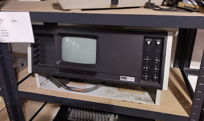
Less expected was this Hermes CRT 4200 computer with built-in screen (the 'CRT') - is that the same Hermes that made the Baby?

And Victor that started-out making massive mechanical adding machines; the name now on a relatively modern (and bland) looking PC of the early 1980s.

The Adler of the push-bar typewriters later joined up with Triumph to become Triumph-Adler or TA. This beige-box is then perhaps a 60-year later descendent of our little Klein-Adler.

Not pictured, but for every decade there were also several game computers of the era displayed as well - and pretty much all working and playable!

But even when not too much into the computer gaming history (of which there is a lot!), this collection manages to impress with an enormous amount of hardware displayed. Great to see so many machines that were 'cool' in their day (or still are, actually :) and some surprising, venerable typewriter brand-names in there as well.

(And if shelves and shelves full of old computer hardware are boring - there is the arcade section with at least 50 machines, all free playable!)

Good visit :-)

Monday, July 14, 2025

Re-keying a Comptometer model J

Another, second Comptometer got a full new keyboard. 

This one is a common model J that was bought as a parts machine - it was severely rusted (all keystems rusted red) and half the columns didn't work. 

But it had good white keys, so these were all harvested to refurbish the Supertotalizer. Having taken its keys, couldn't quite bring myself to 'bin it' - so made an attempt to get it working again.

As often with these machines, deep cleaning of some rods and levers internally got it all working again. All keystems taken out and refreshed (steelwool!) and remaining green keys removed made it look much better - then it needed a full set of 90 new keytops.

The very labour-intensive method for making keys as used before on a model H was too much for this J. Besides, the keys on a model J should not be fully opaque as on a model H. Especially the white cellulose-acetate keys of the J are a bit semi-translucent. So, no expensive resin-printing and lacquering+polishing, but a simple FDM print for this machine.

New 3D models were made, this time suitable for less-hassle FDM printing. Keytop legends were copied from some remaining good specimens. A modern ' hobby printer' can then make pretty good parts, even with a regular 0.4 mm nozzle. The STL files can be downloaded from Printables, with extra hints on print settings.

To do some simple visual smoothing, the keys were given 3 or 4 layers of clear varnish. That also stops the lettering-paint creeping between layers when filling the lettering.

Latex wall-paint again was used, filling the lettering (well, numbering...) - letting it dry, then any spillover on the keytop can be wiped off with a damp cloth. Hold the cloth taut, flat - then it will only soften and take off the paint on the key surface and not draw it out of the recessed lettering.

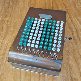
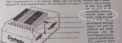
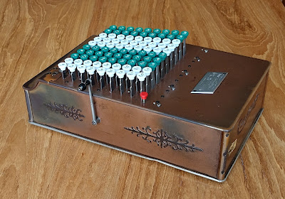
The white and the green plastic is a bit 'bright' still, but the documents of the time do state that the Comptometer had green-white keys, not green-cream! 

Several columns were by the way printed using a raft, which isn't really needed - no rafts gives a cleaner base. Nevertheless; result was a full set of 10 columns of new, reproduction keys in PLA plastic.

Fitted on the machine and comparing side-by-side with aged originals on a 1930s white-green Comptometer, the keys do look very bright - yet this might be what these machines looked like when new.

The new 3D models and method of manufacture really lower the cost for making new keys for a Comptometer. In case one or two keys need replacing, a printed part can of course be painted to be a good colour-match with the rest of the original keys. In case a full keyboard is replaced, this is less critical and ease of manufacture becomes key. (pun!)

Result is that we now have yet another Comptometer; a very common model J - with uncommonly bright keys :-)

Sunday, July 13, 2025

Deciphering a hay tedder - Meccano double puzzle

This one image with a parts list is the instructions for a Hooi Keer Machine, or a hay tedder. Here shown in a 1924 Dutch edition of the Meccano Book 1 of instructions. This model first appeared in 1916 and was replaced by an improved, updated model in 1928.

In style it's a typical early Meccano model; very spidery and 'schematic'. And of course a very period subject, modern horse-drawn farm machinery. Not really knowing offhand in 2025 what a real 1916 hay tedder looked like makes such a small model even more of a puzzle.


It turns out that the right-most (in picture) pulleys are not wheels, but merely end-pieces to hold the axle in. It's a two-wheel contraption (as most tedders of the period were), where one wheel drives a rotary 'rake'-wheel on the right-most rod via a driving band (red). When moving the model the rotary 'rake' really does turn faster than the wheel, actually gives a good illustration of the working principle of a (rotary) hay tedder.

The two bars could suggest a push-cart, but the seat on top I think makes it clear this was meant as a model of a horse-drawn machine.

After 100+ years these small relaxing puzzles have gained an extra dimension; not only how-to-construct, but also 'what-is-it?' :-)

Saturday, July 5, 2025

A 1975 vintage Olympia CD43

Unexpected thrift-store find!

In suitably coloured plastic, a 1975 Olympia CD43.

Spotted by our youngest, who scans the bins of 'button-boxes' for anything cool - this rated cool enough, certainly for the few Euro asking price. Batteries included - and it works :)


The vacuum fluorescent (VFD) display glows crisply green - in a bezel that is a little higher than the keyboard.


This small, simple four-function calculator was manufactured for Olympia in Japan. Noting that although it is a basic calculator with the four functions, in 1975 this was an advanced and relatively expensive item. It works on two AA batteries, but also has a power-jack for an external power-supply.


The arrival of low-cost electronic calculators in 1975 - 1976 spelled the rapid end of mechanical calculators and sliderules alike. This Olympia is reportedly based on the NEC µPD941C integrated circuit; a dual-inline 28 pin package.

This Olympia electronic calculator is in a way a direct descendent of the first commercially succesfull pinwheel calculator, the Odhner of the late 19th century. Setting up a German manufacturing / licensing of the Odhner patents was the basis of the Brunsviga line of calculators in the 1890s and Brunsviga was absorbed by Olympia in the late 1950s.

Showing how it compares; the usual simple division of 355

by 113

gives the answer immediately:

That really shows how much the little electronic calculator was superior to mechanical four-species machines (such as e.g. this Olympia RT4).

This thrift store find came complete with its vinyl protective sleeve.


That sleeve and it probably being kept in a drawer for likely 40-odd years away from direct sunlight is what probably helped keep the beige plastic relatively bright. It will continue to be kept by our youngest out of sunlight in its sleeve :)