Wednesday, January 12, 2022

My most worn wristwatch of 2021

Inspired by Teeritz' re-cap of the year in wristwatches that are always read with interest and nudged by Frank's follow-up, here's my most-worn wristwatch of 2021.

Working from home nearly all the time, didn't wear a watch most days - the one that did get use was my 1935 Elgin with its expansion band. There is some yellowing of the crystal (as is common) that gives a golden hue to the dial. Fortunately there is no corrosion (from the yellowing crystal) and the dial is still perfectly readable and the mechanism runs fine.

The Flex-Let scissor-type expansion band is a bit later than the watch, but these start becoming fashionable by the mid 1930s so not too inappropriate for this watch. It takes some getting used to, but then works very well. Being expanding, it's very comfortable around the wrist.

The Elgin's gold-filled (i.e. thinly plated) case with stepped-sides is very art-deco - overall a nice, usable timepiece when worn with care.

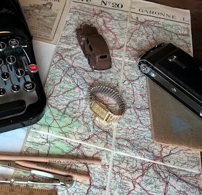
Also in the frame is an equally art-deco period Remington 5 Portable typewriter with the 'Streamline' housing style.

The black-and-chrome Kodak Six-20 from the mid to late 1930s is lying on Junkers documentation for their vibration-free engine. Not quite Bond-level material, but perhaps 'ten days in Paris' or 'night train to Munich' atmosphere :)

The pencils are late 1930s or 40s items from Faber, the ruler is of the same vintage.

The model car is a (reproduction) Dinky Toy number 39a, the Packard Super 8 from the American cars series released in 1939. The background to it all is a late 1920s Carte Taride linen-backed map of the Garonne region of France.

Hadn't considered it before, it's a nice idea; January as Wristwatch Retrospective Month :-)

Friday, January 7, 2022

How not to start fixing up an Erika folding typewriter

After starting to improve and fix-up a nice little Erika folding typewriter, things quickly devolved into this:


The reason for getting to the bare carriage-frame was that one of these little ~3.8mm diameter balls dropped out. That's a ball from the carriage bearing - it has six of these. Once started to take off the carriage, might as well clean and re-assemble the whole thing.


The reason for the little ball-bearing to drop out, was my application of excessive and injudicious force to get the platen rod out - in the process also destroying the pin in the rod that is used to mesh with the platen.


The reason the pin was sheared off, was that the platen-knob was rusted solid onto the rod and needed 'violence' to come off. This made it impossible to feel for the right alignment that would have allowed the pin to pass through a slot of the left carriage-side. (Had I been aware of its existence...)


Additional to being rusted onto the rod, the two set-screws that hold the knob had so rusted as to have effectively fused with the knob. Oil, creeping oil, heat and hammer-tap would not make them move - and being set-screws half of the heads of course broke off. So both screws were drilled out. Unfortunately flat recesses were ground on the rod, so fully drilling out the screws still left some chips in the cavity to block the knob (in addition to it being rusted onto the rod). Hence the resorting to force - which should have been applied more carefully and targeted. Hindsight.


The reason to start this 'improvement' process was that, although the machine typed, it tore any ribbon to shreds with a rock-hard platen. This truly slate-like platen also made it very loud and probably risked damaging the type-slugs. So when wanting to re-cover the platen, it all starts with taking out the cylinder and that needed the platen knob removed with the rusted set-screws. It all kind of developed from there...

On the plus side, the whole carriage assembly is again squeaky clean and polished with new oil and grease where needed. Also the construction is now understood - how it is all supposed to work. Especially that little pin that fits a slot in the line-spacing ratchet is something that'd take a bit of fiddling to find out.

With the now-clean carriage assembled and the paper-bail ruler re-painted with new cream lettering, the parts that I broke were seen to. The ~2mm set-screw holes were drilled out a bit more and new thread was tapped. Mainly because I had 6BA taps and screws handy, this will probably be the only German typewriter with British Association threaded parts on it. A couple of degrees next tot he location of the sheared-off pin, a hole was drilled and a 1.6mm nail-end driven in. This nail-end was then filed to shape, to be a close fit with the slot in the ratchet.


New brass screws were given a nickel finish to fit in. Brass is not really strong enough, but at least they're not going to rust as badly as the original parts!


The small set-screws will probably be replaced by slightly-stronger short screws with a proper head. The margin-release bar however makes it tricky, leaving little room for a screw-head. Best to start with a too-long screw to make shorter than the other way around...


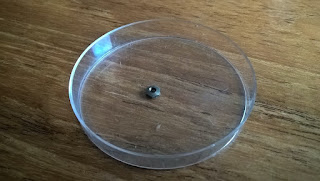
One slightly worrying thing is, that I've one nut left over (diam. ~ 2.3mm in thread). When taking the carriage apart, all sub-assemblies were carefully kept in lots of small plastic bags with their screws and nuts. However, when taking out the margin-bar a small nut seemed to drop unexpectedly, probably somewhere from the left-side of the carriage. I have no idea where that came from or where it should go. The typewriter seems to function fine without this nut, but it is still slightly worrying.


There actually is one spot where a nut is missing - on the backspace levers assembly. The superfluous nut is however too large for this screw-thread (diam. ~ 1.8mm over thread). To further add to the 'discomfort' on all this; when a correct little nut is added to properly tighten this assembly, then the carriage fouls the backspace-mechanism and blocks. So for now it's left as a pivot-bolt without a nut. And a little extra nut in a tray.


Oh, almost as an afterthought - the platen was re-covered with one layer of rubber (inner-tube) and three layers of heat-shrink. The ends were taken off and kept in little bags like all the parts and sub-assemblies. Both marked for rotation so they could be fitted back with the same rotation. Also the feed-roller that was very much not-round got re-covered with heat-shrink layers building up to the right diameter.

Net result of the whole effort was that we had a lot of entertainment out of the machine and -fortunately- are again at a point where the Erika types!  :-)

Sunday, January 2, 2022

From Mr Kennedy's workshop came a small cactus watering can

The maker's mark underneath a small watering-can, a 'cactus watering can', states that it's from Kennedy in Loosdrecht.

Amazingly, on the digitized archives of a local newspaper a photograph could be found of Mr Kennedy's copper-smithy, made in January 1954. The caption stated it is the coppersmith's shop of Mr. Kennedy housed in an old school in Nieuw-Loosdrecht.

Not sure who Mr Kennedy is or if he is even in the picture - the photographer will have stood on a workbench in one corner and instructed the boys to pose with their work. Some of the brightly polished products of the workshop strategically scattered around a workbench - and there on the workbench in front is standing the exact same watering can.

Of course unlikely to be this exact specimen, but it is one of the exact same pattern. And as this was not mass-manufacture, this particular 'cactusgietertje' with the flattened shape sitting on the table here today was very likely made around 1954 too.

These copper body with brass handle+spout watering cans came into fashion from, I think, the 1930s and were most common during the fifties and sixties in The Netherlands. Generally called 'cactus watering cans' (cactusgietertje) they also are found in e.g. Germany, but seem to be less common in most other countries. 

It's nice to be able to 'place' an object and very neat indeed seeing it when new in the place where it was made with the people that made it :)

Saturday, December 18, 2021

Effect of platen hardness on the sound of a typewriter

The sound that typewriters make is determined by the overall design - and by the rubber of the platen or cylinder. To be able to get an impression of the effect of platen rubber, one machine was tested with two new platens of  different hardness.

Especially machines from the 1930s and older will have a platen covered with natural rubber that can harden over time. This hardening makes the typewriter louder and 'sharper'. Additionally a rock-hard platen is harder on the type-slugs, possibly increasing the chance of damage and reduces print-quality. An older platen's surface will often be marked by the type-slugs impact, with pitting of the characters in the surface. 

Re-surfacing a rock-hard platen with new rubber is thus a good thing to do, if feasible. A hardness of between Shore 85 and 90 is I think generally advised for typewriters. When re-surfacing; what would however be the effect of choosing a softer or harder platen if wanting a less-loud machine?

To assess the impact on sound of only the platen hardness, a Remington Portable 2 typewriter was fitted with a new platen with a hardness of about Shore 90. The sound of typing a line halfway down a page was recorded. Then the platen was swapped-out with a new, very soft platen of Shore 80. Again the sound of typing a line halfway the page was recorded in the same set-up. Then the sound recordings were compared, using the Audacity program.

The typewriter was placed on a felt-mat to dampen resonance of the mechanism with the table, relative to the sound of the impact of the type. With its very exposed typebars and typing-point, the sound of the type striking the platen should be dominant - more so than for later, more enclosed typewriters.

Seeing the spectrogram views for both platens side-by-side immediately confirms what could be heard; that the sound is different. The soft platen's energy-peak is at a lower frequency. The hard platen sounds sharp, a crisp clack. The soft platen is a more muffled pop or thup sound with the overall rattle of the machine more noticeable. (Sound snippets in a zip file.)

When comparing graphs of the spectrum of the sound from both platens sized to the same scale, it can be seen that the soft platen is different and indeed also less loud. The volume of the key-strike sounds is lower. The peak of the type-striking sound with a hard platen is from 4 to 6 kHz, whereas the soft platen's peak is in the 2 to 3 kHz range. 

The volume and spectrum of the sound below about 1 kHz is essentially identical for both platens - this is the relatively low-frequency rattle and clanking of the mechanism; noise made by the carriage, keys and whole internal mechanism. (A proper analysis of the captures with e.g. Octave could probably extract much more information, but that'd be taking things a bit far perhaps - not that this is, or is it...)

The graphs incidentally make clear that further reducing the sound of the type-strike becomes less relevant already at this soft-platen's level. The general noise of the whole mechanism is already a major factor for the perceived sound overall.

The graphs do confirm that indeed the typewriter becomes less loud with a softer platen. Having said that, the print quality with a very soft platen does suffer. Also the printing becomes more sensitive to the operator's touch.

For this Portable, the Shore 80 platen is definitely too soft and the print-quality is noticeably lower than the printing with the Shore 90 platen. There is markedly more 'ribbon-fuzz' around the character. With the soft platen the machine needs a very light touch to avoid embossing the paper, so only a fairly light imprint is possible. These drawbacks will almost certainly vary per typewriter model. Not every typewriter and/or type-slug will have the same sensitivity to the platen-material properties. (E.g. on the Underwood 5, a very soft platen worked great - on this RP2 it is too soft really.)

With the very soft platen, the effect of the touch of the typist has a stronger impact on the imprint - to get an even, constant 'blackness' a very even touch is needed. With a harder platen this effect is less pronounced and within a wider range of 'touch' the imprint remains reasonably constant.

Using an extra backing sheet with the soft platen helps to bring the print-qualities closer together.

So overall; as with most engineering things, it is a compromise. The conclusion for now is that softer is indeed quieter, but at the expense of print-quality.

Sunday, December 12, 2021

Carriage height adjustment for the Underwood 3-bank portable

This 3-bank portable typewriter needed to be adjusted. The lowercase did not print fully (bottom-heavy) and the two shifts also did not line up correctly. The machine probably had something heavy stacked onto it or been generally knocked about to 'drive' the carriage lower. (To be fair - any typewriter that looks like this one did, should be expected to need some tuning and adjusting.)

Fortunately the Underwood Standard Portable Typewriter (3 bank) is entirely adjustable - once you find the right screws and order of adjusting them.

The basic approach is to first adjust the carriage baseline height so that the lowercase prints fully. Then the two shifts are adjusted to match the baseline. Finally the lock-functions for the shifts are adjusted. This sounds reasonably simple, but it took a few tries and pensive peering into the mechanism to get it right. (A typewriter repairman could have made some remarks on the fumbling about...  ...but we got there - I think :-)

In the Underwood 3-bank, the baseline is determined by the carriage resting on the Caps-shift levers. This Caps-shift lever in its turn rests on the adjusting screw. The shifted positions are determined by adjusting-screws that stop the upward movement of the lever and carriage. With these three adjustable 'stop-positions' the typewriter can be aligned completely

If the machine is a later model with also a right shift lever, then adjusting-screw 1 in the picture below is probably the one to start with for the adjusting. If the machine has only the left shift-keys, probably start at screw 2 with the same procedure. Loosen the lock-nuts on all adjustment screws 1, 2 and 3 and loosen adjusting-screws 2 and 3, i.e. screw out a few turns to give space for the adjusting. The carriage height is now determined only by screw 1.

This screws in for raising the carriage, out for lowering the carriage. Judging the correct height by only a few characters is quite hard - even with the qpdb-set. When however a couple of lines of text are typed, it becomes easier to detect a bias of the type, e.g. a bottom-bias with the letters 'thicker' at the bottom or a top-bias with thicker/heavier ink at the top. In case of bottom-bias the carriage must be raised, with top-bias it must be lowered. 

Iterating slowly with ever smaller turns of the screw will get the paragraph typed without discernible bias in the printed text. Start e.g. with full turns up or down until overshooting to the other bias, then half a turn the other way, a quarter turn etc. When the paragraph types without bias, tighten the lock-nut to fix the adjustment in position. Best hold the screw with a screwdriver when tightening the lock-nut to prevent accidental turning of the screw and losing the adjustment.

Note: make sure that any bias is not caused by the ribbon. E.g. a ribbon-vibrator that is dirty or out of adjustment could cause the upper-end of characters to not print reliably and give the false impression of bottom-bias!

With the carriage now at its correct baseline height, adjust upwards the screw 2 for the left Caps-shift lever until the key has no 'empty travel' left. Note that there is an extra mechanism in this lever that also has some travel, so best keep an eye on the top of the adjusting-screw inside the machine as it touches the lever. Similarly the screw 3 can be adjusted upwards to remove 'empty travel' of the Fig-shift lever. Then these can then also be lock-nutted in position.

With the baseline now adjusted, the capitals have to be matched. For this, the font-panel of the typewriter should be removed. With the right tools it could probably be done with the panel in-place, but it is much better to work with the panel out of the way for better access and visibility of the parts. (Front panel removed by 5 screws, as in previous post.)

Note: if removing the front-panel, take care to make sure that at least one of the spool-ratchets is 'free', otherwise the ribbon-advance will pull on both spools, jam the ribbon-vibrator and mess up the whole adjusting of the carriage!

The Caps-shift position is determined by the adjustment-screws in a tilting bar on the left and right of the machine. First put the machine in Fig-shift, this tilts the bar forward and brings the Caps adjusting screws into view. The left screw is shown in the picture below, with a spanner of just the right size ready to loosen the lock-nut.

The upper- and lowercase can be tuned by adjusting both at the same time, or one by one. It seemed better to do the fine adjustment one at a time. The left screw is probably best adjusted with the carriage to the left (weight over the screw being adjusted). Typing pairs of Mm, Mn and Rr will quickly show if the lowercase needs to rise higher to match the uppercase or the other way around. With carriage to the right, the right-screw is given the fine-adjustment the same way. It is a bit of a roundabout way, needing to Fig-shift to get at the screws to make the adjustment, then back to baseline and uppercase. With again the approach of iterating with ever smaller turns of the screws, this Caps-shift adjustment should be fairly quick and straightforward.

The Fig-shift alignment is similar - its position is determined by two adjustment screws low in the machine just in front of the carriage. These can be easily reached with a screwdriver, however getting a spanner on the lock-nut is rather tricky. (Long needle-nose pliers may be needed; it is bad workshop-practice but may be the only way.) The picture below shows the left Fig-shift screw, the right screw is similarly inaccessible at the right side of the machine.

Using the comma (lowercase) with the semi-colon (Fig-shift) and the 2 with the m, the Fig-shift position is adjusted to match the baseline carriage height. This works the same way as the Caps-shift adjusting, by making sure the lowercase character rises just enough to match the position of the character printed in the shifted position.

With these seven adjustment screws now all tuned and the baseline, Caps-shift and Fig-shift at the correct (or good enough) setting, the lock-functions can be adjusted. These will likely no longer work as they should, because the retaining tab needs to match the shifted position of the key-lever. The Caps-shift lock bracket is held by by the screws indicated in the yellow oval, the Fig-shift lock by the screws in the blue oval (plus it may need the top of the Caps-shift screws loosened).

The little tab on the shift-lever needs to slide just under the bracket in the slot. The brackets can be adjusted up and down, having long slotted holes where they are screwed to the comb-plate.

With a little tweaking, these brackets can be fixed in a height that the tab slides nicely under the bracket and holds it in the shifted position without any 'sagging'. I.e. there should be no dropping of the carriage when it is held by the shift-lock. It should however be not so tight that a press on the key won't release the tab from the bracket. A bit of tweaking of their positions should make both shift locks work as intended again.

With the typewriter adjusted, it may settle a bit. Typing a page will show up any play or screws that weren't tightened as well as they should. Starting from an already (mostly) adjusted machine, further fine-tuning or fixing becomes easier. The end-result should be an Underwood 3-bank that will again type quite decently.
Sunday, November 21, 2021

Cleaning up the Underwood Standard Portable Typewriter (3-bank) and some first fixes

It is again surprising how much an old typewriter benefits from simply cleaning it. This old Underwood 3-bank Portable looked a right project, with a brownish hue of rust all over the machine.


Much of the rust turned out to be superficial, although some areas are rather pitted and patches have lost all nickel. With basic washing, polishing (Brasso) and the occasional use of fine steel wool, all surfaces came back to a shine. Areas with pitting and plating loss were given the aluminium-treatment. Rubbing with a tightly crumpled wad of aluminium foil will abrade aluminium into the rougher rust areas - this makes nickel-loss much less obvious.

Cleaning also clarified the serial number. Turns out I misread the number and it is a 1926 machine, not a '23. The leading '1' is easily confused for an edge of the stamping tool or missed entirely. My guess is that this is the reason for several early 3-banks with late-model features in The Database.

The bell and margins-stops that were heavily tarnished and pitted have become quite presentable. Even the drawband was given a wash. This sounds somewhat over-the-top perhaps, but the reason was that it was starting to fray at the edge at one spot. To be able to tamp-down the loose threads with latex textile glue, the band was removed and first washed to get rid of grime and dirt. It still is grey, but now the latex had a chance to connect with the fabric instead of with dirt only.

The wayward 'N' keytop and the left shift-keytop were also straightened (Underwood did not make these rings easy to get off, by the way - limpets, the lot of them!...).

There is still the whole typewriter to be adjusted and internals to be cleaned - nothing lines up properly yet. The ribbon-advance is easily accessible and was cleaned thoroughly, the ratchets move freely again. The font panel is by the way fixed with 5 screws (green ring), the rest of the screws are the mounting of the ribbon-reverse (forks with linking-bar).


This machine has been knocked about a bit, the spool-cups were bent and the entire right ribbon capstan was tilted backwards. This capstan is held in a sub-frame and can be straightened by loosening two screws (green ring). To get access to these screws, put the typewriter in 'Fig' double-shift and move one carriage-lever out of the way. Undo its screw (blue ring), then the lever will drop down (blue arrow) to give access.


This typewriter is really a miniature of the regular Underwood machine. At the back it follows the large Underwood 5 style of cast-iron frame with a rectangular cut-out showing the mechanism. Also on the lower frame the list of patents as per standard Underwood practice. This typewriter was exported from the U.S.A. to The Netherlands and there it got yet an extra label noting Dutch patent number 9461. 


This patent was issued in 1923 and indeed is the Dutch version of the frame construction for this Portable. Oddly, this patent number was also applied to Dutch 4-bank Underwood Portables and even to regular Underwood 5 machines.


The screws in the segment were re-fitted correctly. One of these screws was awkwardly screwed in askew. It turned out that this screw (red circle) was forced into a hole that does not have a thread for it.


Somehow somebody switched the two screws; the innermost of the screws on the segment top-edge are the mounting screws; small diameter and long. The second set of screws are larger and very short to only screw into the black bracket. These are the stops to hold the typebar-rod in place. Switched out again and very carefull coaxed back into their damaged threads, they now sit flush again as they should. (The third set of screws fix the brackets that hold the typebar rest.)

The botched screw is evidence that somebody repaired, or at least tinkered with the typewriter in the past. Similarly that missing left paper-finger - this does not just slide off the carriage, but a screw has to be removed for this to come off!

Now to look for a way to give it again a left paper-finger - probably will make an attempt at re-manufacturing the part (this is an unlikely part for anyone have a spare one lying about). And more cleaning and adjusting: it's really a very nice little barn-find project-machine :-)

Monday, November 1, 2021

Opening the Supertotalizer and getting the Comptometer to work (mostly)

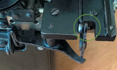
How to open a Comptometer and get access to the mechanism is well documented in several places on the internet. The Supertotalizer is not much different, it starts with removing the front top panel by removing two screws (green circle). The panel can then be lifted off, moving it forward at the same time to slide the two prongs out of the side-beading (green arrow).


Inside this panel are two strips of celluloid, held with thin clamps behind the 'portholes'. Judging from the multiple yellowed patterns, these are probably the original celluloid strips that have been shifted around over the decades. With a bit of puzzling a new position could be found without any cracks visible and not-too-yellow.


The clearing lever for the totalizer-part can be removed by undoing a set-screw that is inside of the case. After removing this lever, best give the set-screw a few turns back in to avoid it getting accidentally lost.


The handles on the right side of the calculator can be taken off by undoing their mounting screws, as is standard for regular Comptometers.


Then the case can be set on its side and the four screws that hold the mechanism in the case can be removed. I've read it is common for Comptometers to have lost some of these screws (they work loose and drop out) and this Supertotalizer also is missing one of the mounting screws. (The other screws in the bottom hold an internal stiffener, the screws at the box-corners hold the sides together - best left untouched.)


With these removed, the complete mechanism can be lifted out of the box. Either slide it out when on its side or grab by the rim of the top plate and lift out. It can snag on the cork padding of the box-sides, but with some wiggling it should come out.

The mechanism of a Comptometer is very well pictured and extensively described on the internet - those pages have been very helpful in getting to grips with this calculator. As others have remarked; this is a remarkably densely packed mechanism!


To get the sluggish columns of the main unit working again, oil was applied to all bearings and quite liberally to the stuck carry-cams. For this, a simple mineral sewing-machine oil was used. Special creeping oil was considered, but did not want to risk mixing and getting 'odd' substances in the machine. The new sewing-machine oil will also evaporate over time, but should be non-gumming. It mixes with and dissolves the old, gummed oil and washes it out - it is hoped to spots where the 'gum' cannot do harm. Continued exercise of the machine will be important for that - as per the first point of advice from The Gramophone Company in the 1920s: "Disuse is bad for the machine".

A piece of soft wire was used to route the oil to the spots deeper inside the machine. Then the numeral wheels were rotated by hand to work the oil into the sluggish bearings. (With the machine zeroed, the rock-frame is tilted forward and all wheels are loose, can be 'twiddled' freely.) This mostly solved the carry-problem of columns 6 to 10, but the first column stubbornly refused to do a carry. Instead always blocking at the 9 to zero point.

With much staring into the mechanism, referencing the pages at John Wolff's Web Museum and viewing a great animation of the mechanism, the culprit was identified to be the zero-stop of the reset-mechanism! This lever is held by a torsion spring against a frame-tab and moved as the rock-frame moves. Maybe this machine got deformed from a few knocks during its time, but with the rock-frame engaged, the zero-stop of column 1 was still in the path of the stop-pin - thus preventing moving from 9 to zero. Very careful forming of the frame-tab resolved the problem of column 1 (further tweaking of the tabs for other columns solved remaining reliability issues there too). Note that a small change in the holding tab has a large effect on the zero-stop position, so very small adjustments only!


To clean bearings without completely taking the mechanism apart, it is recommended to run a rod of the same diameter through the machine to push out a bearing-rod for proper cleaning. 


This actually worked well on the intermediate-gear rods (green circles) - it made the main-mechanism noticeably faster. Thankfully there were no mishaps and no gears fell out of the machine during this process. An old knitting-needle worked well, with a diameter of 2.8mm and the end sawed-off to give a clean push-plane.


The number-wheels and the carry-wheels (yellow circles) however have a smaller rod of 1/16" diameter - have yet to locate a smooth steel 1/16" rod (and pick-up courage) to tackle those. Another thing is that to remove the carry-wheel rod, first the intermediate-gear rod needs to be replaced with a slightly shorter temporary rod. This then allows the holding-brackets to tilt/slide away, releasing the carry-wheel rod.

The totalizer-component was completey seized-up with gummed-up old oil. Extensive tweaking and long stares at the mechanism revealed this was only from the carry-gears being stuck to their axle-rod (red in drawing). The rest of the gears and wheels were easily freed. Applying liberal oil and forcefully working the gears back and forth individually slowly released the columns one by one.


This was a long process, leaving the oil to penetrate inside the gear-wheel bush for several days (with periodic working the wheels) for every column and using prods to get the oil where it has to be. 


In the end, all columns of the totalizer again move freely and the carry works fine. That the old gummed-oil is still on the rod is a worry, it should really be taken out and properly cleaned - but for now this is what could be done. 

A few of the blinds had come unstuck from their peg, with a thin screwdriver their tabs were easily flipped back over the actuating peg (green arrow in picture, green circle/arrow in figure below).

With some extra oil at likely spots and a thorough cleaning of the red correction-button stem, the controlled-key error detection mechanism also started to function as advertised.

The one thing that still won't work, is the main bell. The mechanism is there and seems correct, the rock-frame however just doesn't put enough 'zest' into its engaging-movement to give the hammer enough momentum to strike the bell. We can live without a bell.

The Felt & Tarrant Supertotalizer has now been oiled and continues to be extensively exercised - and all the main functions work again.

Now discovering how to operate it; a fascinating calculator and it's surprisingly fast and capable. 

Typewriters are simple :-)